65 Mustang Restoration
(Very Late)
Yeah I know,,, I'm way behind. I got a ton of things done last year on the car,, let's see if I can get caught up a bit.
So lets start with the addition of the radio amp, starting with the power supply. For this setup we're running power straight from the battery, though it's actually attached to the solenoid post. I spent a lot of time trying to figure out the best routing of the power wire which goes all the way to behind the back seat firewall I installed. This is what I decided on. I like clean, simple, out of the way, protected, and easy to get to, when possible.

All of those extra relays are for the Scott Drake Headlight Upgrade Harness, which takes all of the stress off of your headlight switch so they don't quit on you when the switch gets hot,, especially when you've upgraded to better lighting.

I routed the cable through the battery apron, along the frame and through the passenger floor board, turned to the right & back through the channel covered by the door sill plate,, etc,,
And finally to the new 940 watt, JBL GTO-840EZ amp that I installed on the steel back seat firewall that was previously installed.

I covered both the firewall & the rear speaker dash with a nice vinyl we got from out local fabric shop.


And here it is pretty much all ready to go,, simple clean & out of the way, yet still not too hard to access.
-----------------------------------------------------------------------------------
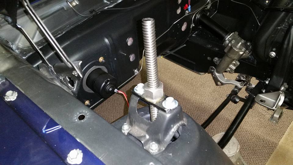
So before I get into the front suspension, I decided since I already didn't have enough to do, that I should probably install some Sub-Frame Connectors that I saw, had to have, and bought.


I decided to bolt them on for now since I already have finished the bottom side of the car, though welding would probably be better,,, However I can see why people don't like to just bolt them in,, whether it's the sad Engineer's fastening design, or the company's choice to cut costs.

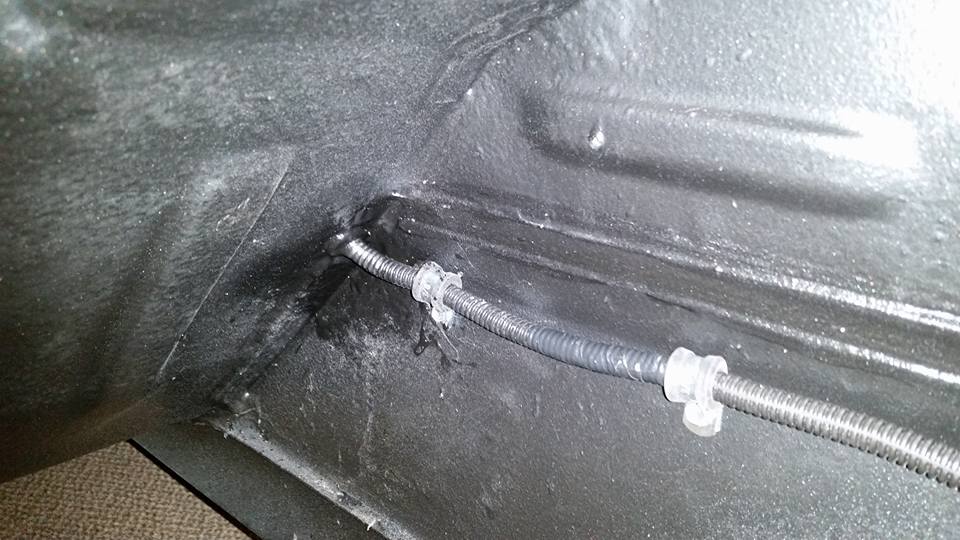
(Above) Take a look at the whimpy nut fasteners that they send with the kit. Notice on the top bracket, that the tiny shiny ring on the nut is the only little bit of surface area that would actually put any clamping pressure on the inside of the floor support(frame),, pittyful! (The nuts don't sit flush with the brackets and are only tacked to them).
So like when most intelligent people add a washer to a nut & bolt combo for every other job known to mankind to help secure & spread the clamping force load,,, that's what I decided to do. So I super glued nice thick washers to the sides of the nuts. This makes it bit tougher to install but I believe it's well worth the effort,,,
"Do it Once & Do it Right!"


(Below) This is the optional X-Brace that you can also run with this kit,, but I'm holing off until I know whether it'll clear my exhaust setup once it's installed. (not my car)

--------------------------------------------------------------------------------------
Front Suspension
Though I have already installed most of the front suspension, this will be more for the front spring options. I will be covering 2 different options here since this restoration is taking so long which gives me to to see/find other newer & better options that are reasonably priced.
OPTION #1

For both options & supposedly better handling, both of the upper control arms received the "Shelby Drop" which was lowering the mounting holes approx. 1 1/4". This should help with Camber Gain which is handy for handling.

The 4 basic components for installing the front factory style springs. The reconditioned upper metal ring, the new insulator, new spring saddles, & the new 300# (pound per inch) GT springs.


This is the front spring installer tool I found on ebay,,, boy did it work nicely! You install this to one of the saddles, slide on the spring, slide it through the spring perch & tighten until you can slip the saddle into the control arm,, pretty easy and a whole lot safer than a lot of other installation methods.


Vwoelah! It's installed and all of my fingers are still attached!
OPTION #2
There are a ton of aftermarket front suspension kits out there, so you can choose what fits your needs & budget. this is the kit that filled my needs. This kit came from CPP (Classic Performance Parts)
| 6470COK-DA | 1964½-70 Mustang, Dual Adjustable, pair |

This is definitely a sweet little kit. I chose the dual adjustable shocks for an extra $50,, just because you never know,, lol.

I still ran the upper metal ring & the new insulator,,, pretty much everything up top is the same.

Where it differs is on the lower end. There's a nice roller bearing that goes between the spring & adjuster ring to help with adjusting the ride height of the vehicle,, which makes it a hundred time easier than Option #1. The springs that we chose when talking to the CPP Tech, were the 350# rate springs,, and to start, we'll set both valves for compression/rebound @ #5. Also, you can see that the saddles are no longer needed.

When I actually got around to adjusting the initial ride height, the adjusting rings were at their lowest setting for installation, I raised the rings about 1 1/4" which seems to have gotten me in the ball park (and yes the engine/transmission were installed when I made this adjustment). (Also, if you talk to their tech, make sure to make them give you a free spanner wrench & possibly a free tee shirt. lol)
---------------------------------------------------------------------------------------
Front Strut Rods Re-designed
I had already installed brand new strut rods & rubber bushings,, and then I saw a you tube video of someone who put a Go-Pro aimed at the strut rod & front suspension,,, and my views quickly changed. Hopefully I can add a link to that video for as long as it's up & running. (You may have to copy & paste)
www.youtube.com/watch?v=gPhRhZYLTpI&index=16&list=PLn0v_Pb_vezzkrsENf64RU6LSBN_CYWa1
After I decided that this was not acceptable for me,, I searched all over for some aftermarket kits,, but everything was $400 and above,, too expensive for me,,, so it was time to use some of my circle track skills.

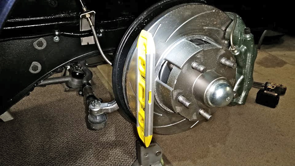
The 1st thing to do was to level the car onto 4 tall jack stands. Then install one of my wheel/tire combos, jack it up to where I want the ride height to be(FYI: I did Before I installed the Option #2 Springs)

Once at height, I put a smaller jack stand & shims under the lower control arm to hold it into position while the tire is removed. Doing this allows for all sorts of things to be able to be seen, measured & done. Things like checking clearances and seeing what will & won't work once you're ready to roll.

While everything is at height (where you will leave it during this whole process), I measured the lower control arm to an area up front,, the idea is that presently with the Non-adjustable strut rods installed,,, this is where the lower arms SHOULD located be after the new adjustable strut rods are installed (just because they're adjustable, it doesn't mean you should use them for major Caster adjusting,, Only very fine tuning). Write these measurements down in your book somewhere.

I had an extra set of good strut rods, I cut them down (if I recall, to around 11" long) & threaded them with a new RH 3/4"-16 Die I bought. (Only need 1 1/2" of threads, found that out later), I bought a couple of these ends on ebay, (with locking nuts)
LH 3/4"-16 Thread x 5/8" Bore, Chromoly Rod End, w/HMS Heim Joints Re-Buildable
I bought a new 5/8" drill bit and drilled holes in the factory bracket to be able to mount the front heims. Once I installed both of the ends, I measured & saw that I needed a 9" long swedge tube for each side,, this allowed at least 1" of threads to be used on each end.


When you tighten the strut rod down to the lower control arm, you may notice that the front heim is not centered in the bracket,, (and remember, this should be approx. where everything sits as the cars sits on the ground in it's normal position.) So that shows you how much stress the stock rod was under while just sitting still,,, at least now it can be in it's relaxed position. I used several washers to find out where it wanted to sit,,, and was then able to use those measurements to replace them with spacers,,, though I'm sure the washers would have also worked just fine.

All totaled, the cost of everything I needed to make these, was only a couple of weeks to get the right parts(I wasn't in a hurry), and about $125 and a couple of hours of designing/building them.
Now for some of the fun stuff!
Till then,, cya!
Opps,, almost forgot, now that the front end is sitting at the approx. height,,, now's a good time to set the camber(somewhat) using a level,, this just lets you get it somewhat close for the alignment shop. You can also try to get the toe setting closer.
Hi, dig the front strut rod upgrade. Assuming you’ve been able to actually drive it for a while now. How is that particular upgrade working out now that you’ve road tested it?
ReplyDelete